9.5 - Type III Recovery Sequence
Module: Type III Low-Pressure Appliances
Technical and examination-topic verification date: August 13, 2026
Primary current authority: Current EPA Section 608 Type III test topics and current Section 608 recovery/service-practice requirements
Exam-preparation focus: Classic Type III recovery details
Course role: Teaches the sequence and equipment relationships used to remove refrigerant from a low-pressure chiller, with emphasis on liquid-first recovery, the large vapor load that remains afterward, recovery-machine condenser cooling, the recovery-device high-pressure cutout, and the chiller water circulation needed during recovery
Learning Objectives
After completing this section, a student should be able to:
- Explain why refrigerant recovery from a low-pressure chiller normally begins with liquid removal when accessible liquid is available and the recovery equipment is configured for it.
- Explain why vapor recovery is still required after bulk liquid has been removed.
- Describe why a low-pressure chiller can contain a large mass of refrigerant vapor even when no liquid refrigerant remains.
- State the classic Type III exam-preparation example that a 350-ton R-11 chiller at 0 psig can still contain about 100 lb of vapor after liquid removal, and recognize this as an illustrative example rather than a universal value.
- Explain the purpose of the recovery-machine condenser and why adequate condenser cooling is essential during vapor recovery.
- State the classic Type III exam-preparation 10 psig high-pressure cutout value for recovery equipment used on low-pressure appliances.
- Distinguish the recovery-machine 10 psig high-pressure cutout from the 15 psig low-pressure recovery-vessel rupture-disc value introduced in Section 9.4.
- Explain why the chiller’s chilled-water and condenser-water circuits must be circulated or otherwise managed during refrigerant evacuation to prevent freezing.
- State the classic Type III operating relationship that the system water pumps, recovery compressor, and recovery condenser cooling water should all be operating during normal low-pressure recovery when the system is configured for circulation.
- Recognize that suspected tube leakage changes the water-management procedure and is addressed in detail in Section 9.6.
- Explain why reaching a temporary pressure value does not automatically mean that all refrigerant has been removed.
- Describe a safe, generalized Type III recovery sequence without inventing a universal hose arrangement, valve position, flow rate, or manufacturer-specific procedure.
Introduction
Recovery from a low-pressure centrifugal chiller differs from recovery from many Type II appliances in two important ways.
First, a large low-pressure chiller can contain a very large refrigerant charge distributed between:
LIQUID REFRIGERANT
+
REFRIGERANT VAPOR
+
REFRIGERANT DISSOLVED IN OIL
Second, as refrigerant pressure is reduced during recovery, refrigerant and water temperatures can fall enough to create a freezing hazard in the chiller heat exchangers.
EPA’s current Type III test-topic page specifically requires technicians to know that:
Recovering liquid at the beginning speeds recovery.
Vapor must also be recovered.
Water must be circulated or removed during evacuation to prevent freezing.
and technicians must know the:
high-pressure cutout level of recovery devices
used with low-pressure appliances.
Classic Type III exam-preparation details include:
R-11 / R-123 recovery
→ LIQUID FIRST
→ VAPOR SECOND
Recovery-unit high-pressure cutout
→ 10 psig
Low-pressure recovery-vessel rupture disc
→ 15 psig
and:
During recovery:
System water pumps ON
Recovery compressor ON
Recovery condenser cooling water ON
These relationships form the core of Section 9.5.
The exact current required final evacuation level for a low-pressure appliance is intentionally reserved for Section 9.9 so that the recovery sequence and the regulatory endpoint are not confused.
Key Concepts
1. Begin With Bulk Liquid Recovery
EPA’s current Type III test topics state that removing liquid at the beginning of the recovery process speeds recovery.
For traditional R-11 and R-123 recovery, the classic sequence is:
Recovery from an R-11 or R-123 system
starts with LIQUID removal
and is followed by VAPOR recovery.
The reason is straightforward.
Liquid refrigerant contains much more refrigerant mass per unit volume than vapor.
If the recovery setup provides access to bulk liquid and the recovery equipment is designed for liquid handling:
remove liquid first
→ remove large refrigerant mass quickly
→ reduce later vapor-recovery load
High-Priority Exam Rule
TYPE III RECOVERY
→ LIQUID FIRST
→ VAPOR SECOND
This is a sequence principle, not permission to force liquid through a recovery machine that is not designed to accept it.
Always follow the recovery-equipment manufacturer’s approved liquid-recovery configuration.
2. Why Liquid Recovery Is Faster
Compare the two phases conceptually.
A volume of liquid refrigerant contains far more mass than the same volume of refrigerant vapor.
Therefore:
LIQUID FLOW
→ high mass-removal rate
while:
VAPOR FLOW
→ much lower refrigerant density
→ lower mass-removal rate for the same volumetric flow
That is why the technician should take advantage of accessible bulk liquid before relying on vapor recovery for the remainder.
Do not confuse:
Liquid recovery is faster
with:
Liquid recovery alone is sufficient
It is not.
Vapor Recovery After Liquid Removal
1. Vapor Must Still Be Recovered
EPA explicitly includes:
Need to recover vapor in addition to liquid
in the current Type III test topics.
After bulk liquid is removed, refrigerant vapor remains throughout the large internal volume of the chiller.
Vapor can remain in:
- Evaporator shell.
- Condenser shell.
- Compressor passages.
- Purge-system passages.
- Refrigerant piping.
- Oil system.
- Other internal spaces connected to the refrigerant circuit.
Therefore:
NO BULK LIQUID VISIBLE
≠
NO REFRIGERANT REMAINS
2. Large Internal Volume Means Large Vapor Mass
A centrifugal chiller can have very large refrigerant-side shell volume.
Even when vapor density is relatively low, a large volume can still contain a substantial refrigerant mass.
A classic exam-preparation example is:
An average 350-ton R-11 chiller at 0 psig can still contain approximately 100 lb of refrigerant vapor after all liquid has been removed.
For this course, use that value as an exam-preparation example, not as a universal engineering calculation.
The actual vapor mass depends on:
- Chiller internal volume.
- Refrigerant identity.
- Refrigerant temperature.
- Absolute pressure.
- Amount of refrigerant dissolved in oil.
- Internal component geometry.
Exam Lesson From the Example
The important conclusion is:
0 psig
+
no visible liquid
≠
refrigerant-free chiller
A large vapor mass can remain.
3. Why Vapor Recovery Becomes Slow
As vapor is removed:
- Chiller pressure decreases.
- Vapor density decreases.
- Refrigerant saturation temperature decreases.
- Remaining liquid films or dissolved refrigerant can continue to vaporize.
- Pressure difference available to move vapor can become smaller.
The recovery machine therefore spends increasing time removing smaller amounts of refrigerant mass.
This is normal near the end of recovery.
A technician should not respond by intentionally venting the remaining vapor.
Generalized Type III Recovery Sequence
A useful teaching sequence is:
1. IDENTIFY refrigerant and recovery requirements
↓
2. PREPARE certified compatible recovery equipment
↓
3. PREPARE recovery vessel and confirm available capacity
↓
4. ESTABLISH chiller water circulation / freeze protection
↓
5. ESTABLISH recovery-machine condenser cooling
↓
6. RECOVER accessible BULK LIQUID
↓
7. TRANSITION to VAPOR recovery
↓
8. CONTINUE water circulation / cooling while pressure falls
↓
9. MONITOR recovery-machine discharge pressure / high-pressure cutout
↓
10. REACH applicable regulatory endpoint
↓
11. STOP / ISOLATE and observe for pressure rise as required
↓
12. CONTINUE recovery if refrigerant remains
↓
13. COMPLETE manufacturer shutdown / clearing procedure
The exact hose connections, valve positions, liquid-transfer method, and recovery-machine operating controls depend on the equipment manufacturer.
Recovery Preparation
1. Identify the Refrigerant
Before recovery:
- Confirm the refrigerant from the chiller nameplate and service documentation.
- Confirm the recovery machine is approved for that refrigerant.
- Confirm the recovery vessel is suitable for the refrigerant and expected pressure.
- Avoid mixing refrigerants.
Do not identify a refrigerant only from pressure or cylinder color.
2. Confirm Recovery-Vessel Capacity
Large chillers can contain large refrigerant charges.
Before recovery:
estimate refrigerant mass to be recovered
→ verify available cylinder / recovery-vessel capacity
→ weigh containers as required
A large Type III job may use a dedicated recovery vessel rather than ordinary small portable recovery cylinders.
The vessel and recovery system must be appropriate for the specific job.
3. Verify Water-System Condition
Before pulling the chiller toward deep vacuum, determine:
- Whether chilled-water flow can be maintained.
- Whether condenser-water flow can be maintained.
- Whether a tube leak is suspected.
- Whether the water sides must instead be drained.
The normal water-circulation relationship is introduced here; the exception for suspected tube leakage is developed fully in Section 9.6.
Chiller Water Pumps During Recovery
1. Why Water Must Be Managed
EPA’s current Type III test topics state that technicians need to:
circulate or remove water from the chiller
while evacuating refrigerant
→ prevent freezing
As refrigerant pressure falls, refrigerant saturation temperature also falls.
The refrigerant side can therefore become cold enough to freeze water remaining inside evaporator or condenser tubes.
2. Normal Circulation Case
In the classic normal-circulation exam scenario, the operating relationship is:
When recovering refrigerant:
SYSTEM WATER PUMPS → ON
RECOVERY COMPRESSOR → ON
RECOVERY CONDENSER WATER → ON
For a normal chiller without a suspected tube leak, circulating water helps prevent localized water freezing as refrigerant temperature drops.
This typically means maintaining appropriate circulation through:
- Chilled-water side.
- Condenser-water side.
according to the chiller/recovery procedure.
Exam Memory Rule
NORMAL TYPE III RECOVERY
→ KEEP CHILLER WATER MOVING
3. Do Not Treat “Pumps On” as Universal Under Every Condition
If tube leakage is suspected, continuing water circulation can introduce more water into the refrigerant circuit.
In the classic Type III exam scenario, the response to suspected tube leakage is:
Drain the water sides of the evaporator and condenser
before refrigerant recovery.
That special case is reserved for Section 9.6.
Therefore:
NO SUSPECTED TUBE LEAK
→ circulate water as required
SUSPECTED TUBE LEAK
→ special drain / freeze-prevention procedure
→ see Section 9.6
Recovery-Machine Condenser
1. Why the Recovery Machine Needs a Condenser
A self-contained recovery machine removes refrigerant vapor from the chiller and compresses it.
After compression, the refrigerant is hotter and at a higher pressure.
The recovery machine must reject heat so that refrigerant can be condensed and transferred efficiently to the recovery vessel.
The simplified recovery-machine path is:
CHILLER VAPOR
→ RECOVERY COMPRESSOR
→ hot higher-pressure vapor
→ RECOVERY-MACHINE CONDENSER
→ refrigerant condenses
→ RECOVERY VESSEL
2. Water-Cooled Recovery Condenser
In the traditional Type III exam model, most low-pressure recovery machines use this arrangement:
WATER-COOLED CONDENSER
In that traditional arrangement, the water-cooled condenser is connected to a municipal water supply.
Treat that as a traditional recovery arrangement, not a requirement that every modern recovery machine must use municipal water.
Modern recovery equipment can vary.
The exam concept is:
Recovery condenser must reject heat effectively
and, for the classic water-cooled Type III recovery setup:
RECOVERY CONDENSER COOLING WATER → ON
3. Why Cooling-Water Flow Matters
If cooling-water flow is inadequate:
recovery condenser rejects less heat
→ refrigerant condenses poorly
→ recovery-machine discharge pressure rises
→ recovery slows
→ high-pressure cutout can trip
Thus:
GOOD CONDENSER COOLING
→ lower recovery-machine discharge pressure
→ better recovery performance
Possible Causes of High Recovery-Machine Pressure
If the recovery unit approaches its high-pressure cutout, check conditions such as:
- Insufficient recovery-condenser water flow.
- Warm cooling water.
- Fouled recovery condenser.
- Closed or restricted cooling-water valve.
- Restricted refrigerant flow toward the recovery vessel.
- Recovery-vessel pressure/temperature.
- Manufacturer-specific valve-position errors.
Do not simply bypass the high-pressure cutout.
Recovery-Machine High-Pressure Cutout
1. Classic Type III Exam-Preparation Value
For Type III exam preparation, use the following classic value:
Recovery unit high-pressure cutout
when evacuating a low-pressure chiller
→ 10 psig
EPA’s current Type III test topics continue to identify the high-pressure cutout level of recovery devices used with low-pressure appliances as required examination knowledge.
For this course’s Type III exam preparation:
RECOVERY-UNIT HIGH-PRESSURE CUTOUT
→ 10 psig
2. What the Cutout Protects
The recovery-machine high-pressure cutout stops or interrupts recovery-machine operation when discharge-side pressure rises too high for the low-pressure recovery setup.
It is a safety/protection control.
It should not be:
- Bypassed.
- Jumpered.
- Reset repeatedly without diagnosis.
- Used as the normal method for controlling recovery flow.
High-Priority Exam Relationship
TYPE III RECOVERY DEVICE
HIGH-PRESSURE CUTOUT
→ 10 psig
Recovery Vessel Rupture Disc
1. Separate 15 psig Recovery-Vessel Value
The classic low-pressure recovery-vessel value is:
LOW-PRESSURE RECOVERY VESSEL
RUPTURE DISC
→ RELIEVES AT 15 psig
This is the classic recovery-equipment value.
2. Do Not Confuse the Two Numbers
| Type III Recovery Component | Classic Exam-Preparation Value |
|---|---|
| Recovery-unit high-pressure cutout | 10 psig |
| Low-pressure recovery-vessel rupture disc | 15 psig |
Memory relationship:
CUTOUT → 10
VESSEL DISC → 15
These values describe a traditional low-pressure recovery setup.
They are not universal ratings for the chiller’s own pressure-relief device.
Why the High-Pressure Cutout Can Trip
1. Inadequate Recovery-Condenser Cooling
One of the most important Type III service relationships is:
Recovery condenser cooling-water flow decreases
→ condensing ability decreases
→ recovery discharge pressure rises
→ 10-psig high-pressure cutout may trip
Therefore, when a low-pressure recovery machine trips on high pressure, do not immediately assume the chiller pressure itself is too high.
Inspect the recovery system.
2. Recovery-Vessel Back Pressure
A warm recovery vessel can increase back pressure against the recovery machine.
A nearly full or improperly managed recovery vessel can also create operating problems.
Follow:
- Recovery-machine instructions.
- Recovery-vessel limits.
- Refrigerant-specific procedures.
3. Restrictions
Restrictions can occur in:
- Recovery hoses.
- Filters.
- Service valves.
- Recovery-machine internal passages.
- Recovery-vessel connections.
A restriction can raise discharge pressure and slow recovery.
Correct Response to Cutout Operation
CUTOUT TRIPS
↓
STOP / DIAGNOSE
↓
check recovery condenser cooling
check vessel condition
check restrictions / valves
↓
correct cause
↓
restart according to manufacturer procedure
Do not bypass the cutout.
Liquid-Recovery Stage
1. Identify a Valid Liquid Path
The liquid-recovery connection depends on chiller design.
Possible manufacturer-approved access can include:
- Evaporator liquid service connection.
- Charging/recovery connection.
- Other designated low-point liquid connection.
Do not infer the correct port solely from physical height.
Use the chiller service manual and valve identification.
2. Transfer Bulk Liquid
When the recovery equipment permits:
CHILLER LIQUID
→ recovery equipment / approved transfer path
→ recovery vessel
Monitor:
- Recovery-vessel weight/capacity.
- Recovery equipment pressures.
- Refrigerant flow.
- Chiller water conditions.
3. Transition Point Is Equipment-Specific
Do not invent a universal pressure at which liquid recovery must stop and vapor recovery must begin.
Transition when:
- Accessible bulk liquid has been removed.
- The approved recovery process calls for vapor recovery.
- Equipment indicators show the liquid stage is complete.
Vapor-Recovery Stage
1. Continue Until the Applicable Endpoint
After bulk liquid is removed:
VAPOR RECOVERY CONTINUES
The recovery machine:
- Draws vapor from the chiller.
- Compresses the vapor.
- Rejects heat in the recovery condenser.
- Condenses refrigerant when conditions permit.
- Transfers refrigerant to the recovery vessel.
2. Expect Long Vapor-Recovery Time
Large low-pressure chillers have large internal vapor volume.
Vapor recovery can therefore represent a substantial portion of total recovery time even though liquid removal removed most of the refrigerant mass quickly.
3. Vapor Can Continue to Form
During recovery, additional vapor can come from:
- Residual liquid films.
- Refrigerant trapped in low points.
- Refrigerant dissolved in oil.
- Refrigerant desorbing from internal surfaces.
Section 9.7 focuses specifically on refrigerant retained in oil.
Water Circulation and Recovery Sequence
1. Classic Normal-Condition Operating Set
A useful three-part exam memory relationship is:
SYSTEM WATER PUMPS
→ ON
RECOVERY COMPRESSOR
→ ON
RECOVERY CONDENSER WATER
→ ON
when refrigerant is being recovered under the normal circulation condition.
2. Why Each One Matters
| Item | Why It Is Operating |
|---|---|
| Chiller system water pumps | Helps keep water moving through chiller tubes and reduce freeze risk |
| Recovery compressor | Provides active refrigerant removal |
| Recovery condenser cooling water | Removes heat from compressed refrigerant and controls recovery discharge pressure |
3. These Are Different Water Functions
Do not confuse:
CHILLER WATER CIRCULATION
→ protects chiller tubes from freezing
with:
RECOVERY CONDENSER COOLING WATER
→ removes heat from recovery-machine refrigerant
They are separate functions even though both involve water flow.
Pressure-Rise Check After Reaching the Endpoint
EPA’s current Type III test topics state that after reaching the required recovery vacuum, technicians need to:
wait a few minutes
→ observe whether system pressure rises
A pressure rise can indicate:
- Liquid refrigerant remains in the system.
- Refrigerant remains dissolved in oil.
- Refrigerant is still vaporizing from internal surfaces.
The exact regulatory evacuation level is covered in Section 9.9.
The conceptual sequence is:
Reach required endpoint
↓
Stop / isolate as instructed
↓
Observe pressure
↓
Pressure rises?
If yes:
refrigerant may remain
→ resume recovery as required
Do not interpret every pressure rise as proof of an external leak.
Moisture and leakage can also affect pressure behavior, which Section 9.9 will distinguish in detail.
Freeze-Prevention Boundary With Section 9.6
Section 9.5 establishes only the normal recovery relationship:
circulate or properly manage water
while pulling refrigerant pressure down
Section 9.6 will explain why freezing becomes increasingly dangerous as saturation temperature falls and will cover the special case:
SUSPECTED TUBE LEAK
→ drain water sides before recovery
Do not apply the normal “keep pumps on” rule blindly when a water-to-refrigerant tube leak is suspected.
Recovery Troubleshooting
Recovery Is Slow During Vapor Stage
Possible normal reason:
low vapor density + large internal volume
Possible service causes:
- Restricted recovery hose.
- Restricted filter.
- Inadequate recovery condenser cooling.
- Warm recovery vessel / high back pressure.
- Incorrect valve position.
- Refrigerant still trapped in oil or internal low points.
Recovery Machine Trips at High Pressure
Check:
- Recovery-condenser cooling-water flow.
- Cooling-water temperature.
- Recovery-vessel pressure/temperature.
- Hose and filter restrictions.
- Valve positions.
- Manufacturer troubleshooting procedure.
Do not bypass the cutout.
Chiller Pressure Stops Falling
Possible causes include:
- Continued vaporization from residual refrigerant.
- Refrigerant dissolved in oil.
- Recovery-machine capacity limitation.
- Restrictions.
- Insufficient heat transfer.
- Air leakage into a deeply evacuated low-pressure chiller.
Use the whole system condition rather than one pressure reading alone.
Important Terms
Bulk Liquid Recovery
Bulk liquid recovery is the early stage of refrigerant recovery in which accessible liquid refrigerant is removed before the remaining vapor. It generally removes refrigerant mass much faster than vapor-only recovery.
High-Pressure Cutout
A high-pressure cutout is a protective control that stops or interrupts recovery-machine operation when discharge-side pressure rises too high. The classic Type III exam-preparation value for low-pressure recovery equipment is 10 psig.
Low-Pressure Recovery Vessel
A low-pressure recovery vessel is a refrigerant-receiving vessel designed for low-pressure recovery service. The classic Type III exam-preparation rupture-disc relief value for this vessel is 15 psig.
Recovery Compressor
A recovery compressor is the compressor inside a self-contained recovery machine that draws refrigerant vapor from the chiller and raises its pressure for heat rejection and transfer to the recovery vessel.
Recovery-Machine Condenser
A recovery-machine condenser rejects heat from compressed refrigerant vapor so the refrigerant can condense and be transferred efficiently to the recovery vessel. Classic Type III exam preparation emphasizes water-cooled recovery condensers.
Vapor Recovery
Vapor recovery is the removal of refrigerant in the vapor phase after or in addition to bulk liquid recovery. It is essential because a large low-pressure chiller can retain substantial vapor mass after liquid is gone.
Figures and Diagrams
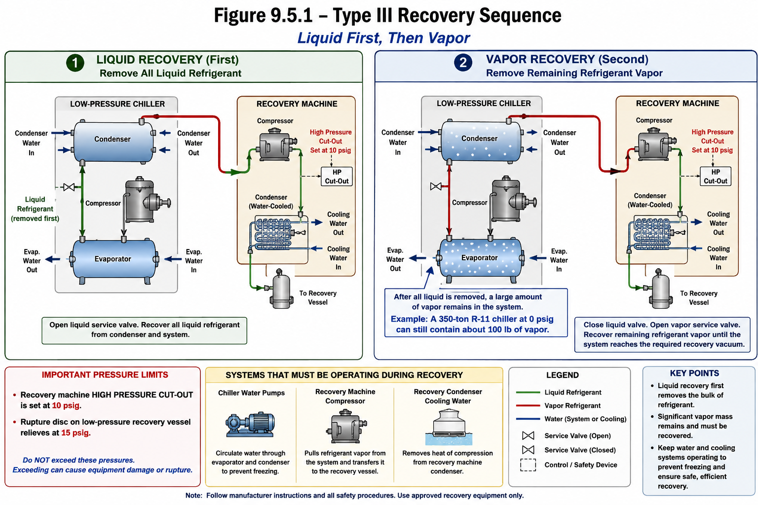
Figure 9.5.1 - Type III liquid-first and vapor-recovery sequence with chiller-water circulation and recovery-machine condenser protection.
AI-generated instructional figure: It may contain visual inaccuracies. Use the accompanying lesson text and cited authoritative sources to verify technical and regulatory details.
EPA 608 Exam Focus
What Students Must Remember
- EPA’s current Type III test topics say recover liquid at the beginning because it speeds recovery.
- Vapor must still be recovered after the liquid is removed.
- In the classic Type III sequence for R-11 or R-123, remove accessible liquid first, then recover vapor.
- A large low-pressure chiller can contain substantial refrigerant vapor after all bulk liquid is gone.
- Classic exam-preparation example: a 350-ton R-11 chiller at 0 psig can still contain about 100 lb of vapor after liquid removal.
- The
100 lbvalue is an example, not a universal chiller value. - Water must be circulated or removed during low-pressure evacuation to prevent freezing.
- In the classic normal-circulation exam scenario:
- System water pumps ON.
- Recovery compressor ON.
- Recovery condenser water ON.
- Many traditional low-pressure recovery machines use a water-cooled recovery condenser.
- Recovery-condenser cooling removes heat from compressed refrigerant and helps control discharge pressure.
- Classic Type III recovery-unit high-pressure cutout:
10 psig
- Classic low-pressure recovery-vessel rupture disc:
15 psig
- Do not confuse these recovery-equipment values with the chiller’s leak-test pressure or its actual installed relief-device rating.
- If the recovery machine trips on high pressure, check cooling-water flow, recovery-vessel condition, restrictions, and valve positions; do not bypass the cutout.
- After reaching the required recovery endpoint, wait a few minutes and observe for pressure rise.
- Pressure rise can indicate refrigerant remains as liquid or is still coming out of oil.
- The exact current Type III evacuation endpoint is taught in Section 9.9.
High-Priority Relationships
TYPE III RECOVERY
→ LIQUID FIRST
→ VAPOR SECOND
NO LIQUID
≠
NO REFRIGERANT
RECOVERY COMPRESSOR
→ RECOVERY CONDENSER
→ RECOVERY VESSEL
RECOVERY-UNIT CUTOUT
→ 10 psig
RECOVERY-VESSEL RUPTURE DISC
→ 15 psig
NORMAL RECOVERY
→ SYSTEM WATER PUMPS ON
→ RECOVERY COMPRESSOR ON
→ RECOVERY CONDENSER WATER ON
ENDPOINT REACHED
→ wait a few minutes
→ pressure rises?
→ refrigerant may remain
Typical Exam Question Patterns
Students may be asked to:
- Select liquid first as the fastest initial Type III recovery method.
- Explain why vapor recovery is required after liquid removal.
- Recognize that a large vapor mass can remain in a low-pressure chiller.
- Recall the classic 350-ton R-11 / 100-lb vapor example.
- Identify the purpose of the recovery-machine condenser.
- Identify cooling-water loss as a cause of rising recovery-machine discharge pressure.
- Recall 10 psig as the low-pressure recovery-unit high-pressure cutout.
- Recall 15 psig as the low-pressure recovery-vessel rupture-disc value.
- State that chiller water pumps and recovery condenser water are operating during the normal recovery condition.
- Recognize that suspected tube leakage changes the water-management procedure.
- Interpret a pressure rise after the required endpoint as evidence that refrigerant may remain.
High-Risk Words
Pay particular attention to:
- Liquid first
- Vapor
- Substantial
- 350 ton
- 100 lb
- Recovery condenser
- Cooling water
- High-pressure cutout
- 10 psig
- Recovery vessel
- Rupture disc
- 15 psig
- Water pumps
- Freeze
- Pressure rise
Common Mistakes and Confusing Points
Mistake 1: Stopping Recovery After Bulk Liquid Is Gone
A large amount of vapor can remain.
Type III recovery requires both liquid and vapor removal.
Mistake 2: Assuming 0 psig Means the Chiller Is Empty
The classic 350-ton R-11 example demonstrates that a large vapor mass can remain at 0 psig.
Mistake 3: Treating the 100-lb Vapor Example as Universal
It is an illustrative exam-preparation example for one representative chiller condition.
Actual vapor mass varies with refrigerant, pressure, temperature, and internal volume.
Mistake 4: Confusing the Chiller Compressor With the Recovery Compressor
The recovery compressor is part of the external recovery machine.
Do not operate the chiller’s normal refrigeration compressor as the refrigerant recovery machine unless a manufacturer-approved system specifically uses an internal pump-out arrangement.
Mistake 5: Forgetting Recovery-Condenser Cooling Water
In the traditional low-pressure recovery setup, condenser cooling water must flow so the recovery machine can reject heat.
Mistake 6: Confusing Chiller Water Pumps With Recovery-Condenser Water
They serve different purposes:
- Chiller water circulation → freeze protection.
- Recovery condenser water → heat rejection / discharge-pressure control.
Mistake 7: Bypassing the Recovery-Unit High-Pressure Cutout
The classic cutout value is 10 psig.
If it trips, diagnose the cause.
Mistake 8: Applying 15 psig to the Recovery-Unit Cutout
15 psig belongs to the classic low-pressure recovery-vessel rupture disc.
The classic recovery-unit cutout value is 10 psig.
Mistake 9: Applying 15 psig to the Chiller’s Own Rupture Disc
Here, the classic 15 psig exam-preparation value identifies the recovery-vessel rupture disc.
Actual chiller relief-device ratings are equipment-specific.
Mistake 10: Running Water Pumps Blindly When a Tube Leak Is Suspected
Suspected tube leakage can require draining the water sides before recovery.
See Section 9.6.
Mistake 11: Ignoring a Pressure Rise After Reaching the Endpoint
Pressure rebound can indicate refrigerant remains as liquid or dissolved in oil.
Mistake 12: Inventing a Universal Liquid-to-Vapor Transition Pressure
No single transition pressure applies to every chiller and recovery machine.
Follow the approved recovery procedure.
Mistake 13: Using the Type III Recovery-Equipment Pressure Values as the Regulatory Evacuation Endpoint
10 psig and 15 psig here describe recovery-equipment protection.
The current required low-pressure appliance evacuation level is a different value taught in Section 9.9.
Concept-Check Questions
Question 9.5-1
What is the preferred initial refrigerant-removal phase when recovering from a low-pressure chiller and accessible liquid is available?
A. Recover bulk liquid first.
B. Recover vapor only from the beginning.
C. Vent the vapor and recover only the oil.
D. Run the chiller compressor until the system reaches atmospheric pressure.
Question 9.5-2
Why must vapor recovery continue after all accessible liquid refrigerant has been removed from a low-pressure chiller?
A. A substantial refrigerant vapor mass can remain in the large internal volume of the chiller.
B. Vapor recovery is required only to cool the condenser water.
C. Removing liquid automatically creates noncondensables that must be vented.
D. The recovery vessel cannot accept liquid refrigerant.
Question 9.5-3
In the classic exam-preparation example, approximately how much refrigerant vapor can remain after liquid recovery from an average 350-ton R-11 chiller at 0 psig?
A. Approximately 1 lb of vapor
B. Approximately 10 lb of vapor
C. Approximately 100 lb of vapor
D. No vapor remains at 0 psig
Question 9.5-4
What is the principal function of the recovery-machine condenser during vapor recovery?
A. Remove heat from compressed recovered refrigerant so it can condense and be transferred to the recovery vessel
B. Circulate chilled water through the building
C. Raise the chiller evaporator pressure for charging
D. Remove oil from the chiller compressor bearings
Question 9.5-5
What is the classic high-pressure cutout setting of a recovery unit used while evacuating a low-pressure chiller?
A. 0 psig
B. 5 psig
C. 10 psig
D. 15 psig
Question 9.5-6
Which statement correctly distinguishes the two classic Type III recovery-equipment pressure values?
A. The recovery-unit high-pressure cutout is 15 psig and the recovery-vessel rupture disc is 10 psig.
B. The recovery-unit high-pressure cutout is 10 psig and the low-pressure recovery-vessel rupture disc is 15 psig.
C. Both values describe the current regulatory evacuation endpoint.
D. Both values are universal rupture-disc settings for the chiller itself.
Question 9.5-7
In the classic normal-circulation Type III exam scenario, which operating combination is correct?
A. Chiller water pumps off; recovery compressor off; recovery condenser water off
B. Chiller water pumps on; recovery compressor on; recovery condenser cooling water on
C. Chiller water pumps off; recovery compressor on; recovery condenser water off
D. Chiller water pumps on; recovery compressor off; recovery condenser water off
Question 9.5-8
After the required recovery endpoint has been reached and the technician waits a few minutes, the chiller pressure rises. What should be considered?
A. Refrigerant may still remain as liquid or may be coming out of the oil, so additional recovery may be required.
B. The chiller is necessarily completely empty.
C. The recovery-vessel rupture disc must have opened.
D. The technician should vent the remaining vapor to stop the pressure rise.
Answers and detailed explanations will be provided in
9.15 - Answers and Explanations.md.
Section Summary
The Type III recovery sequence begins with:
BULK LIQUID RECOVERY
because liquid removal removes refrigerant mass quickly.
It is followed by:
VAPOR RECOVERY
because substantial refrigerant vapor remains after the liquid is gone.
A classic exam-preparation example is:
350-ton R-11 chiller
at 0 psig
→ about 100 lb vapor can still remain
This illustrates the principle rather than defining every chiller.
During vapor recovery:
CHILLER VAPOR
→ RECOVERY COMPRESSOR
→ RECOVERY-MACHINE CONDENSER
→ RECOVERY VESSEL
The traditional low-pressure recovery-machine condenser is water cooled, so adequate cooling-water flow is essential for controlling recovery-machine discharge pressure.
The classic Type III recovery-equipment values are:
RECOVERY-UNIT HIGH-PRESSURE CUTOUT
→ 10 psig
and:
LOW-PRESSURE RECOVERY-VESSEL RUPTURE DISC
→ 15 psig
For the classic normal-circulation exam scenario, remember:
SYSTEM WATER PUMPS → ON
RECOVERY COMPRESSOR → ON
RECOVERY CONDENSER WATER → ON
The chiller water circulation helps prevent freezing, while recovery-condenser water removes heat from the recovered refrigerant.
If a tube leak is suspected, the water-management procedure changes and the water sides may need to be drained before recovery. That special case is developed next:
Section 9.6 - Freeze Prevention During Recovery.
References
Current EPA and Regulatory Sources
-
U.S. Environmental Protection Agency, Test Topics, current Type III Recovery Techniques and Recovery Requirements, verified August 13, 2026.
-
U.S. Environmental Protection Agency, Stationary Refrigeration Service Practice Requirements, current recovery/service-practice framework and current low-pressure evacuation table, verified August 13, 2026.
-
U.S. Environmental Protection Agency, Required Level of Evacuation of Appliances, current low-pressure evacuation requirement; numerical endpoint intentionally deferred to Section 9.9, verified August 13, 2026.
-
U.S. Environmental Protection Agency, Refrigerant Recovery and Recycling Equipment Certification, current recovery-equipment certification framework, verified August 13, 2026.
Project Teaching and Exam-Preparation Sources
-
International Training Institute / project OCR copy, EPA Section 608 Study Guide, Type III
Recovery Techniquessection. This source supports the classic exam-preparation relationships used here: R-11/R-123 liquid-first then vapor recovery; the 350-ton R-11 / approximately 100-lb vapor example; recovery-unit high-pressure cutout at 10 psig; low-pressure recovery-vessel rupture disc at 15 psig; water circulation to prevent freezing; traditional water-cooled recovery condenser; system water pumps, recovery compressor, and recovery condenser water on during recovery; and draining evaporator/condenser water sides before recovery if tube leakage is suspected. -
Rex Miller and Mark R. Miller, HVAC Licensing Study Guide, 3rd ed., general refrigerant recovery, refrigeration machinery, water-cooled condenser, pressure-control, and safe service principles.
-
Edward G. Pita, Air Conditioning Principles and Systems: An Energy Approach, 4th ed., centrifugal-chiller, refrigerant state, heat-transfer, and water-cooled condenser fundamentals.
-
Section 9.4 - Low-Pressure Leak Detection and Pressurization.
-
Section 5.3 - Recovery Equipment Certification and Service Fittings.